InstaSprink Design · BS 9251:2021
Residential sprinkler design, from floor plan to finished drawings.
Lay out BS 9251:2021 sprinkler systems in your web browser. Heads placed and checked as you go, pipework laid out for you, the whole system shown in realistic 3D, and drawings and reports ready to issue.
- Category 1 and 2
- Realistic 3D view
- Preliminary hydraulics
- Nothing to install
- PC, Mac and tablet
Download the InstaSprink Design brochure
Already have an account? Sign in at app.instasprink.com
Overview
Design faster. Check as you go. Issue with confidence.
InstaSprink Design takes a residential sprinkler system through seven clear steps, from the architect's plans to a full set of drawings and a preliminary hydraulic report. It does the repetitive work — placing and dimensioning heads, routing the pipework, finding the operating heads, drawing the system in 3D and filling in the title block — so your time goes on the design decisions.
Start from any plan
Drop in a PDF, PNG or JPG. Set the scale from one dimension and line the floors up.
Heads placed for you
Mark out a room and the heads are placed, spaced and dimensioned to the head's listed coverage.
Live coverage checks
Spacings, wall distances and uncovered areas show in red the moment anything is out.
Pipework laid out
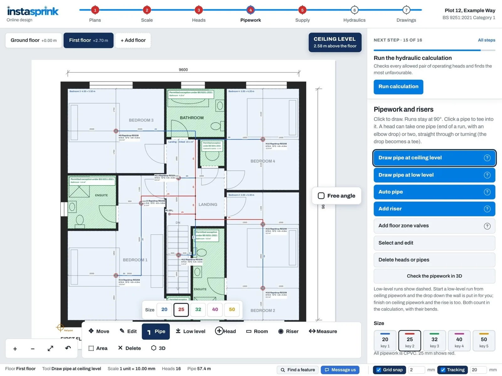
Auto pipe runs a square 25 mm main and 20 mm branches to every head, with another route a click away.
See it in realistic 3D
Every floor, riser, branch and head, with the tank and pump set in place. Turn it, check it, put it on the drawing.
Preliminary hydraulics
Operating heads found and every combination checked against the supply, ready to confirm in your calculation software.
Plans and scale
Start from the plans you already have
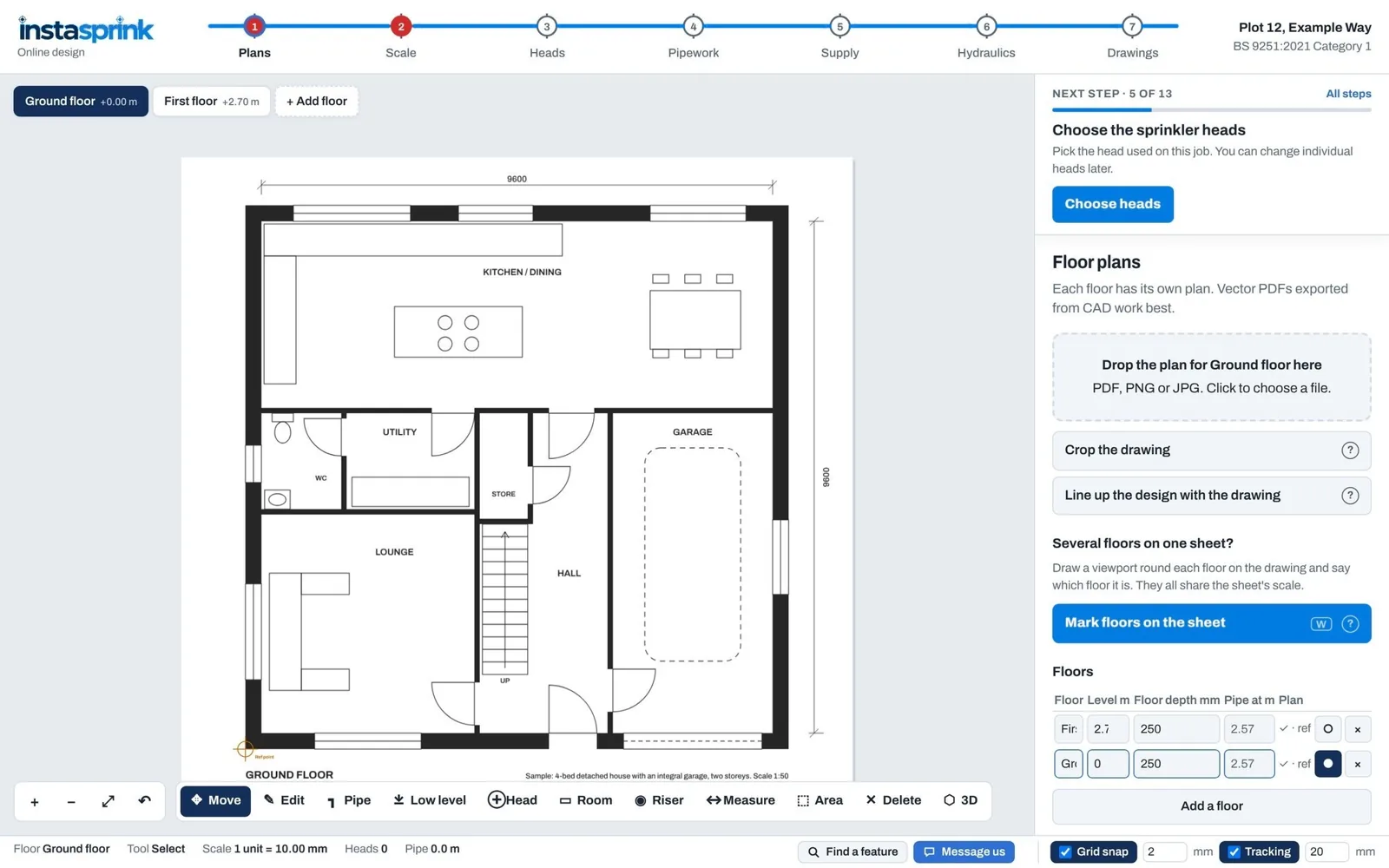
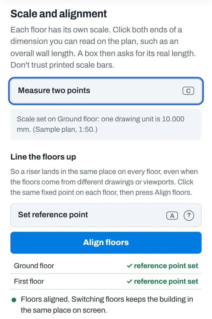
Drop each floor's plan into the tool. A PDF straight from CAD works best, or use a PNG or JPG. Click both ends of a dimension you can read to set the scale, then click one fixed point on each floor so risers land in the same place on every level.
- Multi-page PDFs and drawings with several floors on one sheet
- Floors lined up from one reference point, so a riser drawn on one floor lands in the same place on every other
- Revised drawings drop straight in. Your design and its scale carry over, the old drawing shows in red over the new one, and Line it up fixes any shift
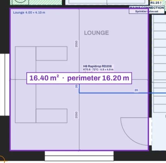
- Measure and Area tools for any distance, area or perimeter on the plan
Sprinkler heads
Mark a room. The heads place themselves.
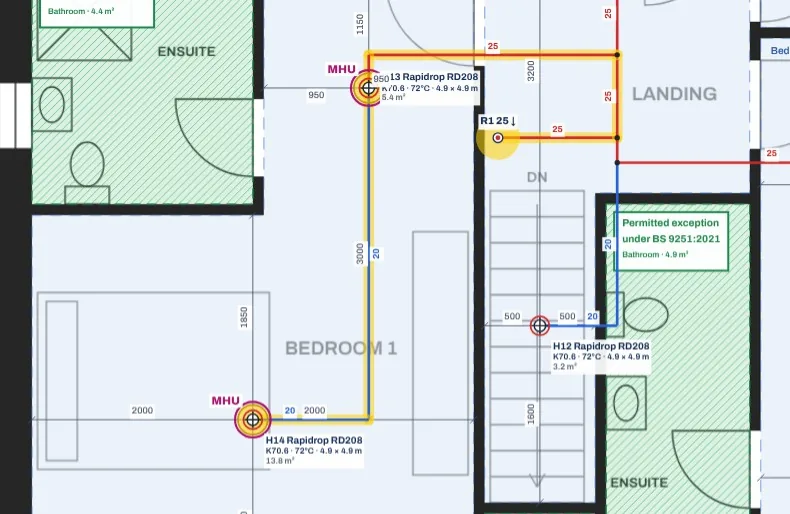
Drag a box for a rectangular room, or click round the corners of any other shape. Live dimensions and alignment guides keep the outline square. Close it and the heads are placed at the right spacings, with every head-to-head and head-to-wall dimension drawn on.
- Head library of Rapidrop, Viking and Victaulic pendent and sidewall heads, with each coverage setting. Add your own to the company library
- Drag a head too far and another of the same kind comes in to cover the gap. Drag it back and it goes again
- Permitted exceptions under BS 9251:2021, such as small bathrooms and cupboards, marked and listed
- Open rooms between floors, such as a hall and landing, linked as one fire compartment
- Sloping ceilings, one slope or two to a ridge, with heads at their true heights
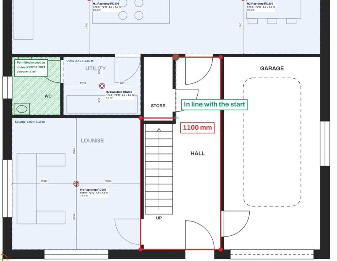
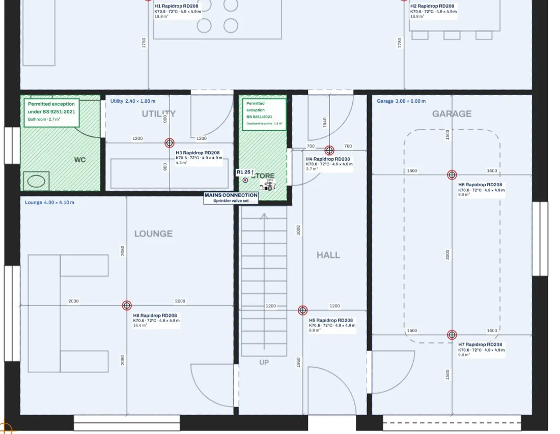
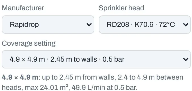
Change a head and it tells you. Swap to a head that covers less and what's no longer covered shows in red. One click re-places the room's heads, and pipes them in again if they were piped.
Pipework and risers
Pipework, laid out for you
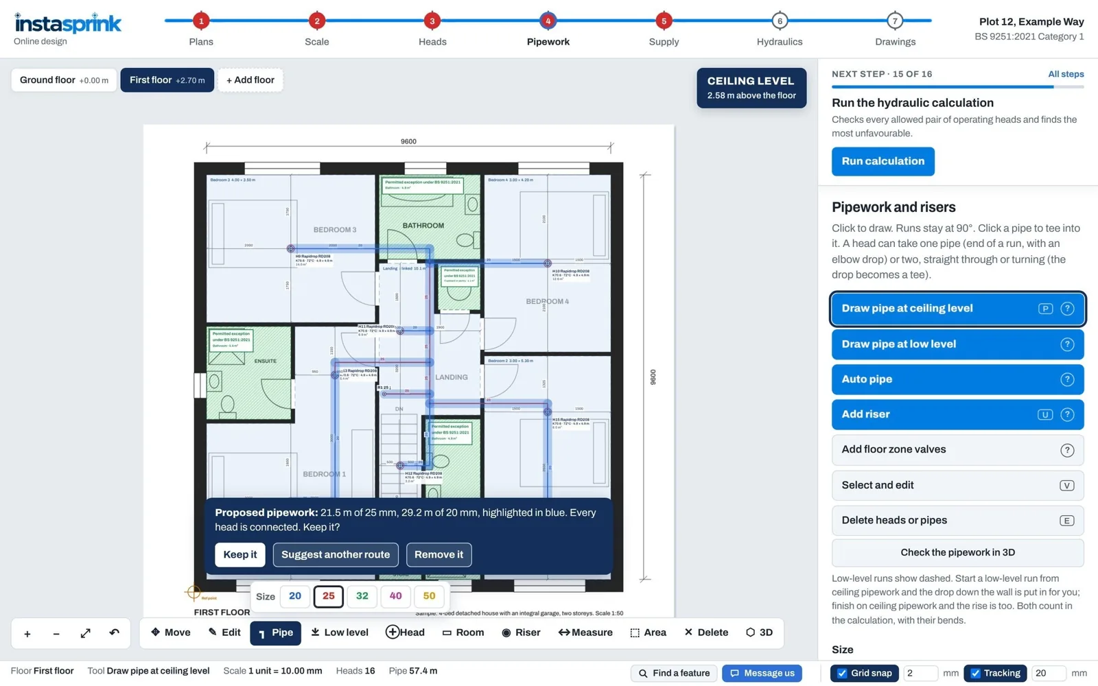
Auto pipe works out the shortest square network from the riser to every head: a 25 mm main down the hall or landing and 20 mm branches to single heads. Keep it, ask for another route, or draw your own — runs stay at 90° and every tee and elbow is counted.
- Heads are never the corner of a run. Every head sits in line on a tee or at the end of a run, the way an installer would fit it
- Risers carry the pipework between floors, with the rise drawn and counted
- Low-level runs with the drops down the wall put in for you, and floor zone valves for larger buildings
- Sized as you choose: a 25 mm main with 20 mm to single heads, or all in 25 mm
- Every fitting counted — tees, elbows, reducers and head adaptors — carried through to the materials list
Realistic 3D view
See the whole system before anyone picks up a pipe cutter
One click turns the plan into a 3D view of the installation: every floor in place, the riser climbing between them, each branch in its true size and colour, every head on its drop, and the tank and pump set where they will go.
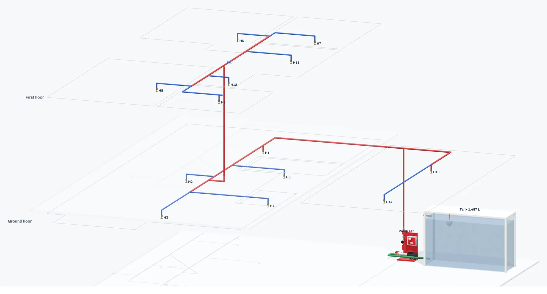
Floors on or off
Views from any side, so a riser or a congested corner can be looked at on its own.
Click to find it
Hover to name any head or pipe; click it and the plan jumps to it.
Nothing to model
Built from the design you've already drawn — tank and pump drawn to size — so it's always up to date.
Supply and preliminary hydraulics
Preliminary hydraulics, as you design
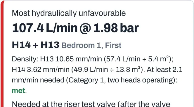
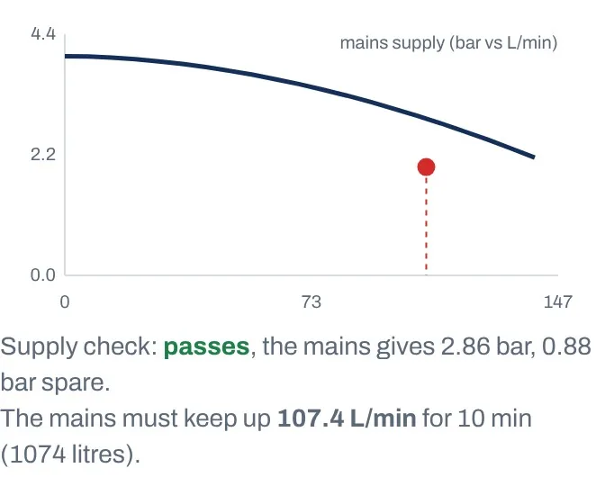
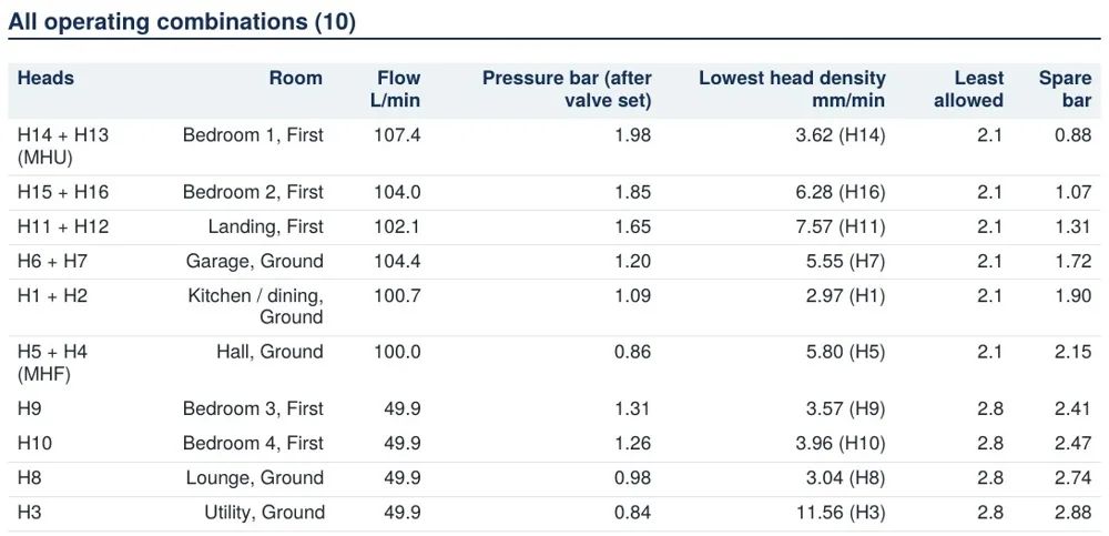
Choose how the system is fed: straight from the mains, boosted mains, or a dedicated tank and pump. Run the preliminary calculation and the operating heads are worked out for you, every combination is checked against the supply, and the result shows what the system needs and how much is to spare.
- Mains: enter the flow test and the valve set; the supply curve is drawn for you
- Tank and pump: fire pump sets and their curves built in, with the tank sized and checked, including proven infill
- MHU and MHF found; every head checked for flow, pressure and design density, Category 1 or 2
- Fitting losses to BS 9251:2021 Table B.6, with each pipe's calculation shown
- Balance heads: swap to lower-flow heads where coverage allows, without making the MHU harder
- Export for your hydraulic calculation software, with the pipe data file to match
For assistance with the design, not the final word. The built-in hydraulics are preliminary: they help you arrive at a layout that works. The calculation must be confirmed in your preferred hydraulic calculation software before issue, and the tool exports the system ready for that.
Drawings and reports
Drawings and reports, ready to issue
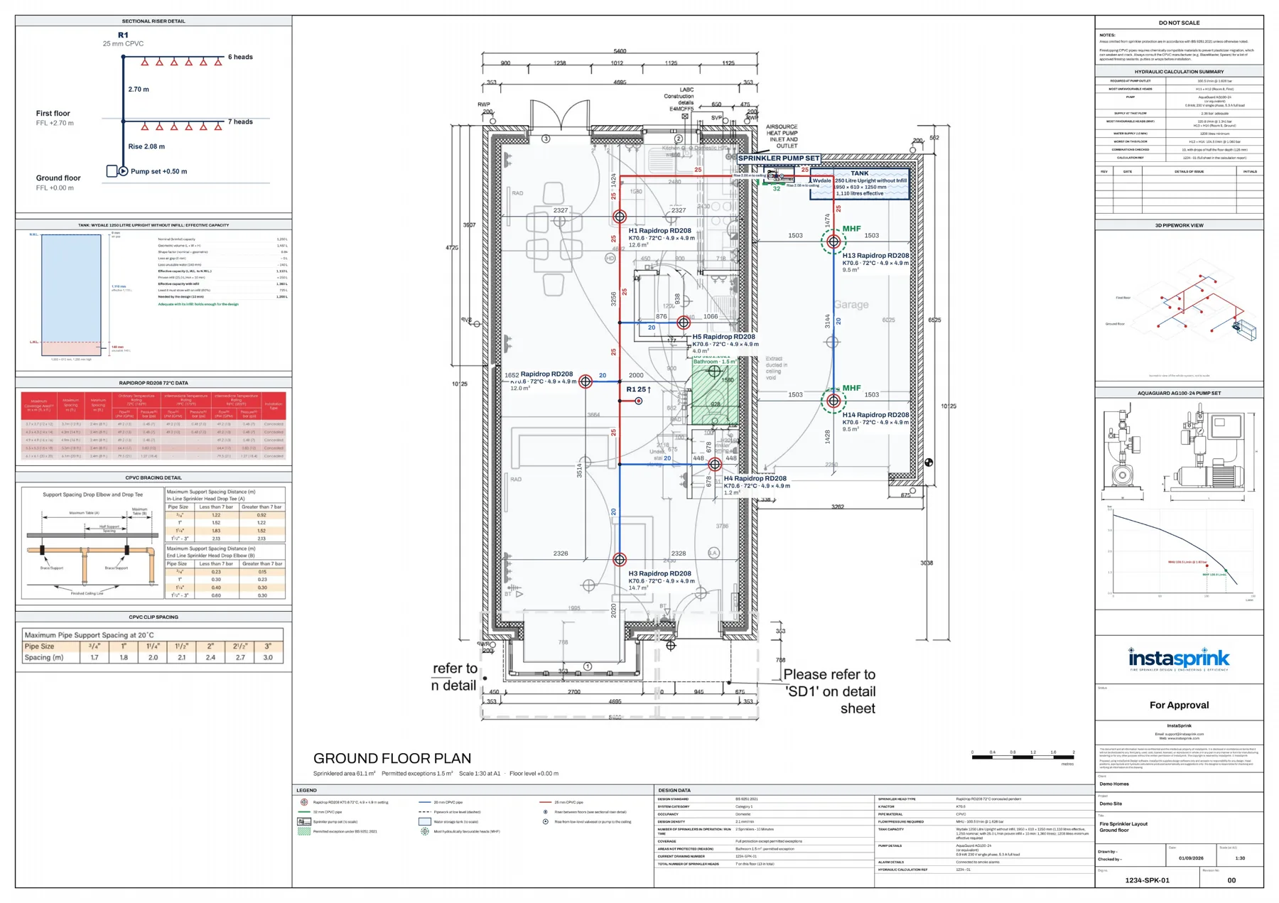
Each floor goes on its own A1 or A3 sheet at a true scale, with your company's title block and logo filled in from the project, and the details an approving body expects alongside the plan. Download the set as one PDF, with the preliminary hydraulic report and an estimated materials list.
- Sectional riser detail, tank effective capacity and head data table
- CPVC bracing and clips, MHU and MHF heads, legend and design data
- Notes and calculation summary, 3D pipework view, pump set and curve
- Title block and revisions, with an issue status on every sheet
For Construction and As Installed open once InstaSprink has verified your company's design competency.
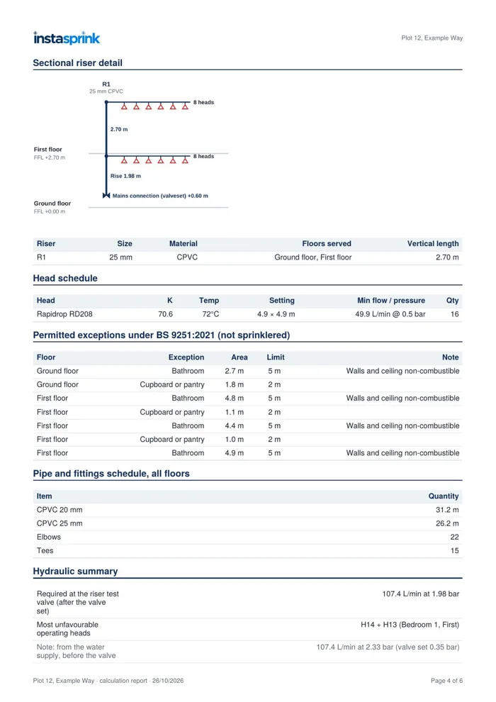
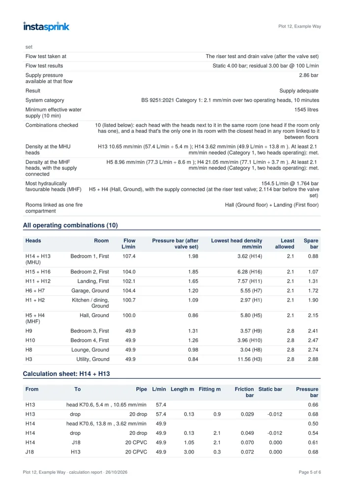
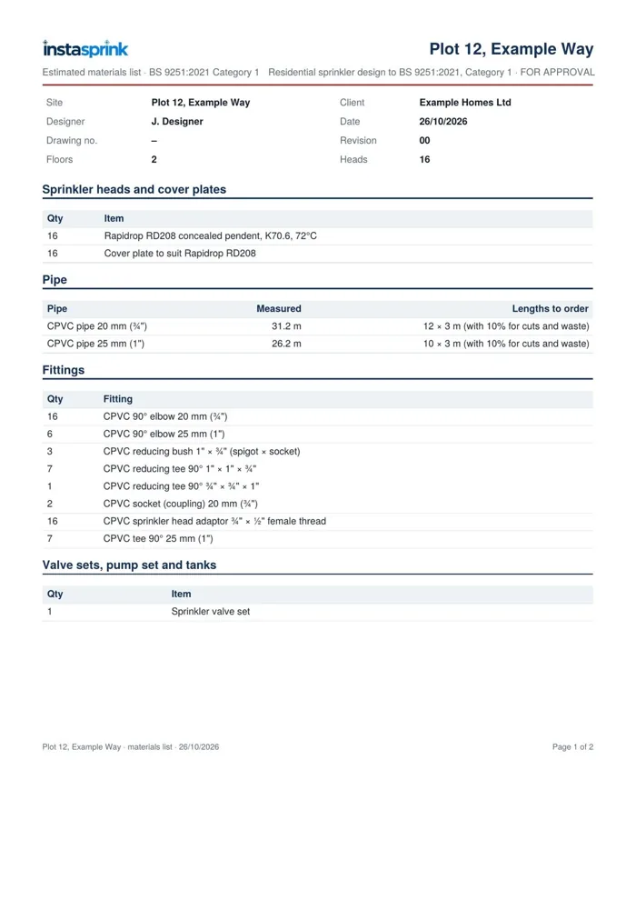
Preliminary report: layouts, riser detail and schedules · every combination and the MHU calculation sheet · materials list.
Built for the way you work
Nothing to install. Your whole team on one login.
Made for touch as well as a mouse, so the same project opens on a tablet on site or a big screen in the office, with every change saved to the company account.
Runs in your browser
On a PC, Mac or tablet, or installed as an app. Projects save to your company account, ready to pick up anywhere.
Seats for your designers
Named seats for the people who design, and free view-only users who can open, check and download.
Help where you need it
Find a feature (Ctrl+K) answers “how do I…?” and takes you to the button. Message us from inside the tool.
Design competency
Verified companies issue drawings For Construction and As Installed.
Straightforward pricing
£99 per seat / month if you sign up by 30 April 2027, fixed for 12 months (standard price £149). Or £35 per design. Estimate included free. See pricing
Your branding
Your logo, address and confidentiality text on every drawing, filled in once for the whole company.
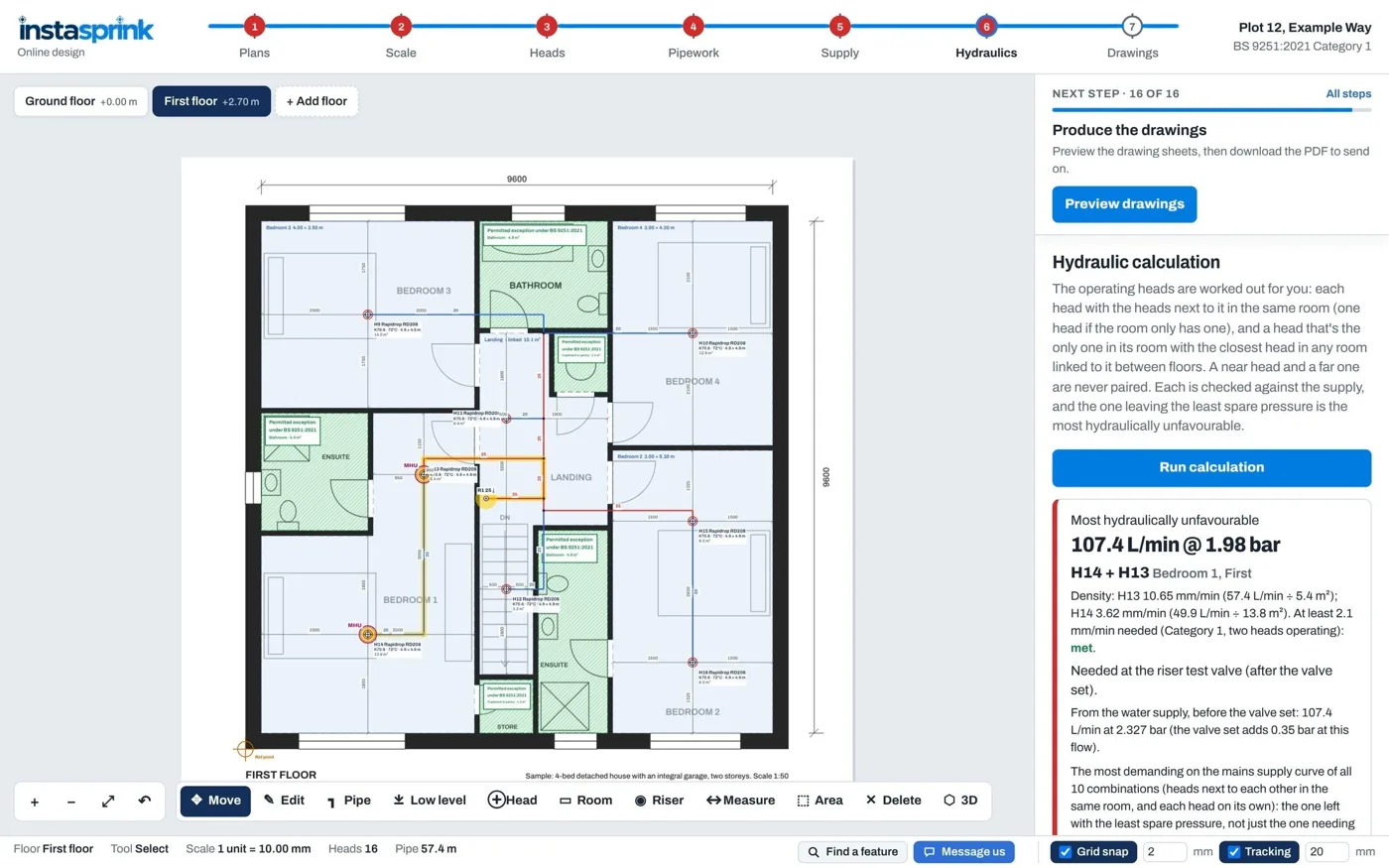
Try it on your next project
Start your free 14-day trial of InstaSprink Design
Create an account at app.instasprink.com and start a full trial, so you can run a real job through it from plans to drawings.
- info@instasprink.com
- Sign up or sign in
- app.instasprink.com
- Web
- instasprink.com
InstaSprink supplies design software only and accepts no responsibility for any design: head positions, pipe layouts and hydraulic calculations produced automatically are preliminary and are suggestions for a competent designer to check and verify, with the hydraulic calculation confirmed in the designer's preferred hydraulic calculation software before issue. Screens show sample projects. Rapidrop, Viking and Victaulic are trademarks of their respective owners.